It is not really a big deal, but sometimes can be useful...
Autoleveling is mostly intended for engraving surfaces that are not totally flat or when you need high precision in depths, for example pcb, engraving metals, etc.
Using bCNC Autolevel feature you can "scan" a surface and get a grid of points representing the surface.
When you send gcode bCNC takes care to add or substract the z values previously readed to the z values in gcode, so the real surface, flat or not will be aligned with gcode Z=0.
This works with any surface, even if they are quite curved, see my previous entry: Engraving Curved Surfaces.
But now i want to use this feature to scan an object and build a mesh surface out of this data:
To test this "3D Scanner" i used a terrain model that can be suitable to my probe:
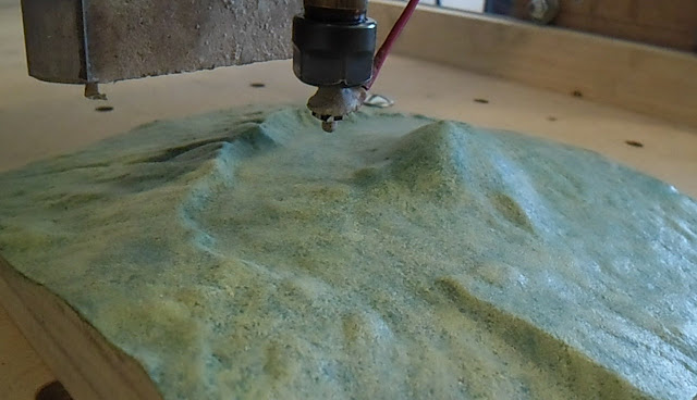
This probe is just a push switch taken from a circuit, glued an small ball to the button and glued to a 6mm screw... fast and cheap to do, but with limitations.
For exanple it can not be used for too step surfaces.
But is more accurate than i spected, repeating same reading i ussually have an error < 0.05 mm. most of the times around 0.01mm.
Doing the scan in bCNC is easy for this task.
Just open bCNC, connect to the board, move the grant to the origin of the area to scan and set X=0, Y=0.
Then Set Z=0 in the highest part of the surface.
Now go to Probe->Autolevel and set the size of the area to scan.
Be sure you set Z depth down enought to hit all the parts of the surface.
Also set the number of readings in X and Y axis and feed rate:

I scanned a 50x50 mm surface in steps of 1 mm, this makes a total of 2601 readings, wich will take long time.
For me took almost 2 hours at 350 mm/m feed rate.. may be i should use 500, but be aware the faster the less accurate will be the readings.

One interesting thing about this is that you can save this data to a file.
Watching this file you can see that is just a list of xyz coordinates for each reading, one point for line:
-15 15 5
-15 15 10
-6 1 150
-15 -15 -5.2335
-7.5 -15 -5.2305
0 -15 -5.2145
7.5 -15 -5.2705
15 -15 -5.2475
In adition to the readings there are 3 points (3 first lines) representing the origin.
We can just delete this 3 first lines to get only the surface points.
If we rename the file.probe we got from bCNC to file.xyz we will be able to open it in Meshlab and see a point cloud.

Getting a surface out of
this point clould is just one click away in Meshlab.
Just go to Filters->Remeshing..blah blah->Surface Reconstruction: Ball Pivoting.
Aply the filter with default parameters, and you get the surface.
I got the faces inverted, so i had to aply another filter:
Filters->Normals...blah blah->Invert Faces Orientation.

Now just save the mesh as stl ot whatever you want and you can use it in other programs.
Watch the video here: https://youtu.be/Wcd_2kM8lJ0
Autoleveling is mostly intended for engraving surfaces that are not totally flat or when you need high precision in depths, for example pcb, engraving metals, etc.
Using bCNC Autolevel feature you can "scan" a surface and get a grid of points representing the surface.
When you send gcode bCNC takes care to add or substract the z values previously readed to the z values in gcode, so the real surface, flat or not will be aligned with gcode Z=0.
This works with any surface, even if they are quite curved, see my previous entry: Engraving Curved Surfaces.
But now i want to use this feature to scan an object and build a mesh surface out of this data:
To test this "3D Scanner" i used a terrain model that can be suitable to my probe:

This probe is just a push switch taken from a circuit, glued an small ball to the button and glued to a 6mm screw... fast and cheap to do, but with limitations.
For exanple it can not be used for too step surfaces.
But is more accurate than i spected, repeating same reading i ussually have an error < 0.05 mm. most of the times around 0.01mm.
Doing the scan in bCNC is easy for this task.
Just open bCNC, connect to the board, move the grant to the origin of the area to scan and set X=0, Y=0.
Then Set Z=0 in the highest part of the surface.
Now go to Probe->Autolevel and set the size of the area to scan.
Be sure you set Z depth down enought to hit all the parts of the surface.
Also set the number of readings in X and Y axis and feed rate:

I scanned a 50x50 mm surface in steps of 1 mm, this makes a total of 2601 readings, wich will take long time.
For me took almost 2 hours at 350 mm/m feed rate.. may be i should use 500, but be aware the faster the less accurate will be the readings.

One interesting thing about this is that you can save this data to a file.
Watching this file you can see that is just a list of xyz coordinates for each reading, one point for line:
-15 15 5
-15 15 10
-6 1 150
-15 -15 -5.2335
-7.5 -15 -5.2305
0 -15 -5.2145
7.5 -15 -5.2705
15 -15 -5.2475
In adition to the readings there are 3 points (3 first lines) representing the origin.
We can just delete this 3 first lines to get only the surface points.
If we rename the file.probe we got from bCNC to file.xyz we will be able to open it in Meshlab and see a point cloud.

Just go to Filters->Remeshing..blah blah->Surface Reconstruction: Ball Pivoting.
Aply the filter with default parameters, and you get the surface.
I got the faces inverted, so i had to aply another filter:
Filters->Normals...blah blah->Invert Faces Orientation.

Now just save the mesh as stl ot whatever you want and you can use it in other programs.
Watch the video here: https://youtu.be/Wcd_2kM8lJ0
Comments
Post a Comment